MediaPipe Objectron
{: .no_toc }
Table of contents
{: .text-delta } 1. TOC {:toc}Attention: Thank you for your interest in MediaPipe Solutions. We have ended support for this MediaPipe Legacy Solution as of March 1, 2023. For more information, see the MediaPipe Solutions site.
Overview
MediaPipe Objectron is a mobile real-time 3D object detection solution for everyday objects. It detects objects in 2D images, and estimates their poses through a machine learning (ML) model, trained on the Objectron dataset.
 objectron_shoe_android_gpu.gif |
  objectron_chair_android_gpu.gif |
  objectron_camera_android_gpu.gif |
  objectron_cup_android_gpu.gif
:——————————————————————————–: | :———————————————————————————-: | :————————————————————————————: | :——————————————————————————:
Fig 1a. Shoe Objectron | Fig 1b. Chair Objectron | Fig 1c. Camera Objectron | Fig 1d. Cup Objectron
objectron_cup_android_gpu.gif
:——————————————————————————–: | :———————————————————————————-: | :————————————————————————————: | :——————————————————————————:
Fig 1a. Shoe Objectron | Fig 1b. Chair Objectron | Fig 1c. Camera Objectron | Fig 1d. Cup Objectron
Object detection is an extensively studied computer vision problem, but most of the research has focused on 2D object prediction. While 2D prediction only provides 2D bounding boxes, by extending prediction to 3D, one can capture an object’s size, position and orientation in the world, leading to a variety of applications in robotics, self-driving vehicles, image retrieval, and augmented reality. Although 2D object detection is relatively mature and has been widely used in the industry, 3D object detection from 2D imagery is a challenging problem, due to the lack of data and diversity of appearances and shapes of objects within a category.
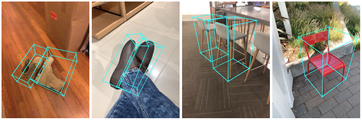 objectron_example_results.png |
:———————————————————————–: |
Fig 2. Objectron example results. |
objectron_example_results.png |
:———————————————————————–: |
Fig 2. Objectron example results. |
Obtaining Real-World 3D Training Data
While there are ample amounts of 3D data for street scenes, due to the popularity of research into self-driving cars that rely on 3D capture sensors like LIDAR, datasets with ground truth 3D annotations for more granular everyday objects are extremely limited. To overcome this problem, we developed a novel data pipeline using mobile augmented reality (AR) session data. With the arrival of ARCore and ARKit, hundreds of millions of smartphones now have AR capabilities and the ability to capture additional information during an AR session, including the camera pose, sparse 3D point clouds, estimated lighting, and planar surfaces.
In order to label ground truth data, we built a novel annotation tool for use with AR session data, which allows annotators to quickly label 3D bounding boxes for objects. This tool uses a split-screen view to display 2D video frames on which are overlaid 3D bounding boxes on the left, alongside a view showing 3D point clouds, camera positions and detected planes on the right. Annotators draw 3D bounding boxes in the 3D view, and verify its location by reviewing the projections in 2D video frames. For static objects, we only need to annotate an object in a single frame and propagate its location to all frames using the ground truth camera pose information from the AR session data, which makes the procedure highly efficient.
|  objectron_data_annotation.gif |
| :————————————————————————–: |
| Fig 3. Real-world data annotation for 3D object detection. (Right) 3D bounding boxes are annotated in the 3D world with detected surfaces and point clouds. (Left) Projections of annotated 3D bounding boxes are overlaid on top of video frames making it easy to validate the annotation. |
objectron_data_annotation.gif |
| :————————————————————————–: |
| Fig 3. Real-world data annotation for 3D object detection. (Right) 3D bounding boxes are annotated in the 3D world with detected surfaces and point clouds. (Left) Projections of annotated 3D bounding boxes are overlaid on top of video frames making it easy to validate the annotation. |
AR Synthetic Data Generation
A popular approach is to complement real-world data with synthetic data in order to increase the accuracy of prediction. However, attempts to do so often yield poor, unrealistic data or, in the case of photorealistic rendering, require significant effort and compute. Our novel approach, called AR Synthetic Data Generation, places virtual objects into scenes that have AR session data, which allows us to leverage camera poses, detected planar surfaces, and estimated lighting to generate placements that are physically probable and with lighting that matches the scene. This approach results in high-quality synthetic data with rendered objects that respect the scene geometry and fit seamlessly into real backgrounds. By combining real-world data and AR synthetic data, we are able to increase the accuracy by about 10%.
 objectron_synthetic_data_generation.gif |
:——————————————————————————————-: |
Fig 4. An example of AR synthetic data generation. The virtual white-brown cereal box is rendered into the real scene, next to the real blue book. |
objectron_synthetic_data_generation.gif |
:——————————————————————————————-: |
Fig 4. An example of AR synthetic data generation. The virtual white-brown cereal box is rendered into the real scene, next to the real blue book. |
ML Pipelines for 3D Object Detection
We built two ML pipelines to predict the 3D bounding box of an object from a single RGB image: one is a two-stage pipeline and the other is a single-stage pipeline. The two-stage pipeline is 3x faster than the single-stage pipeline with similar or better accuracy. The single stage pipeline is good at detecting multiple objects, whereas the two stage pipeline is good for a single dominant object.
Two-stage Pipeline
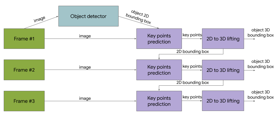
Our two-stage pipeline is illustrated by the diagram in Fig 5. The first stage uses an object detector to find the 2D crop of the object. The second stage takes the image crop and estimates the 3D bounding box. At the same time, it also computes the 2D crop of the object for the next frame, such that the object detector does not need to run every frame.
 objectron_network_architecture.png |
:—————————————————————————————-: |
Fig 5. Network architecture and post-processing for two-stage 3D object detection. |
objectron_network_architecture.png |
:—————————————————————————————-: |
Fig 5. Network architecture and post-processing for two-stage 3D object detection. |
We can use any 2D object detector for the first stage. In this solution, we use TensorFlow Object Detection trained with the Open Images dataset. The second stage 3D bounding box predictor we released runs 83FPS on Adreno 650 mobile GPU.
Single-stage Pipeline
 objectron_network_architecture.png |
:———————————————————————————: |
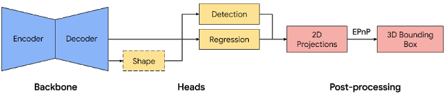
Fig 6. Network architecture and post-processing for single-stage 3D object detection. |
objectron_network_architecture.png |
:———————————————————————————: |
Fig 6. Network architecture and post-processing for single-stage 3D object detection. |
Our single-stage pipeline is illustrated by the diagram in Fig 6, the model backbone has an encoder-decoder architecture, built upon MobileNetv2. We employ a multi-task learning approach, jointly predicting an object’s shape with detection and regression. The shape task predicts the object’s shape signals depending on what ground truth annotation is available, e.g. segmentation. This is optional if there is no shape annotation in training data. For the detection task, we use the annotated bounding boxes and fit a Gaussian to the box, with center at the box centroid, and standard deviations proportional to the box size. The goal for detection is then to predict this distribution with its peak representing the object’s center location. The regression task estimates the 2D projections of the eight bounding box vertices. To obtain the final 3D coordinates for the bounding box, we leverage a well established pose estimation algorithm (EPnP). It can recover the 3D bounding box of an object, without a priori knowledge of the object dimensions. Given the 3D bounding box, we can easily compute pose and size of the object. The model is light enough to run real-time on mobile devices (at 26 FPS on an Adreno 650 mobile GPU).
 objectron_sample_network_results.png |
:————————————————————————————-: |
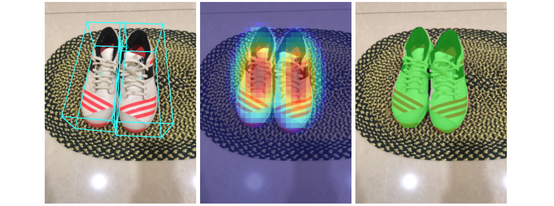
Fig 7. Sample results of our network — (Left) original 2D image with estimated bounding boxes, (Middle) object detection by Gaussian distribution, (Right) predicted segmentation mask. |
objectron_sample_network_results.png |
:————————————————————————————-: |
Fig 7. Sample results of our network — (Left) original 2D image with estimated bounding boxes, (Middle) object detection by Gaussian distribution, (Right) predicted segmentation mask. |
Detection and Tracking
When the model is applied to every frame captured by the mobile device, it can suffer from jitter due to the ambiguity of the 3D bounding box estimated in each frame. To mitigate this, we adopt the same detection+tracking strategy in our 2D object detection and tracking pipeline in MediaPipe Box Tracking. This mitigates the need to run the network on every frame, allowing the use of heavier and therefore more accurate models, while keeping the pipeline real-time on mobile devices. It also retains object identity across frames and ensures that the prediction is temporally consistent, reducing the jitter.
The Objectron 3D object detection and tracking pipeline is implemented as a MediaPipe graph, which internally uses a detection subgraph and a tracking subgraph. The detection subgraph performs ML inference only once every few frames to reduce computation load, and decodes the output tensor to a FrameAnnotation that contains nine keypoints: the 3D bounding box’s center and its eight vertices. The tracking subgraph runs every frame, using the box tracker in MediaPipe Box Tracking to track the 2D box tightly enclosing the projection of the 3D bounding box, and lifts the tracked 2D keypoints to 3D with EPnP. When new detection becomes available from the detection subgraph, the tracking subgraph is also responsible for consolidation between the detection and tracking results, based on the area of overlap.
Objectron Dataset
We also released our Objectron dataset, with which we trained our 3D object detection models. The technical details of the Objectron dataset, including usage and tutorials, are available on the dataset website.
Solution APIs
Cross-platform Configuration Options
Naming style and availability may differ slightly across platforms/languages.
static_image_mode
If set to false, the solution treats the input images as a video stream. It
will try to detect objects in the very first images, and upon successful
detection further localizes the 3D bounding box landmarks. In subsequent images,
once all max_num_objects objects are detected and the
corresponding 3D bounding box landmarks are localized, it simply tracks those
landmarks without invoking another detection until it loses track of any of the
objects. This reduces latency and is ideal for processing video frames. If set
to true, object detection runs every input image, ideal for processing a batch
of static, possibly unrelated, images. Default to false.
max_num_objects
Maximum number of objects to detect. Default to 5.
min_detection_confidence
Minimum confidence value ([0.0, 1.0]) from the object-detection model for the
detection to be considered successful. Default to 0.5.
min_tracking_confidence
Minimum confidence value ([0.0, 1.0]) from the landmark-tracking model for the
3D bounding box landmarks to be considered tracked successfully, or otherwise
object detection will be invoked automatically on the next input image. Setting
it to a higher value can increase robustness of the solution, at the expense of
a higher latency. Ignored if static_image_mode is true,
where object detection simply runs on every image. Default to 0.99.
model_name
Name of the model to use for predicting 3D bounding box landmarks. Currently
supports {'Shoe', 'Chair', 'Cup', 'Camera'}. Default to Shoe.
focal_length
By default, camera focal length defined in NDC space, i.e., (fx, fy). Default to (1.0, 1.0). To specify focal length in
pixel space instead, i.e., (fx_pixel, fy_pixel), users should
provide image_size = (image_width, image_height) to enable
conversions inside the API. For further details about NDC and pixel space,
please see Coordinate Systems.
principal_point
By default, camera principal point defined in NDC space, i.e.,
(px, py). Default to (0.0, 0.0). To specify principal point in
pixel space, i.e.,(px_pixel, py_pixel), users should provide
image_size = (image_width, image_height) to enable
conversions inside the API. For further details about NDC and pixel space,
please see Coordinate Systems.
image_size
Specify only when focal_length and
principal_point are specified in pixel space.
Size of the input image, i.e., (image_width, image_height).
Output
detected_objects
A list of detected 3D bounding box. Each 3D bounding box consists of the following:
landmarks_2d: 2D landmarks of the object’s 3D bounding box. The landmark coordinates are normalized to[0.0, 1.0]by the image width and height respectively.landmarks_3d: 3D landmarks of the object’s 3D bounding box. The landmark coordinates are represented in camera coordinate frame.rotation: rotation matrix from object coordinate frame to camera coordinate frame.translation: translation vector from object coordinate frame to camera coordinate frame.scale: relative scale of the object alongx,yandzdirections.
Python Solution API
Please first follow general instructions to install MediaPipe Python package, then learn more in the companion Python Colab and the usage example below.
Supported configuration options:
- static_image_mode
- max_num_objects
- min_detection_confidence
- min_tracking_confidence
- model_name
- focal_length
- principal_point
- image_size
import cv2
import mediapipe as mp
mp_drawing = mp.solutions.drawing_utils
mp_objectron = mp.solutions.objectron

# For static images:
IMAGE_FILES = []
with mp_objectron.Objectron(static_image_mode=True,
                            max_num_objects=5,
                            min_detection_confidence=0.5,
                            model_name='Shoe') as objectron:
  for idx, file in enumerate(IMAGE_FILES):
    image = cv2.imread(file)
    # Convert the BGR image to RGB and process it with MediaPipe Objectron.
    results = objectron.process(cv2.cvtColor(image, cv2.COLOR_BGR2RGB))

    # Draw box landmarks.
    if not results.detected_objects:
      print(f'No box landmarks detected on {file}')
      continue
    print(f'Box landmarks of {file}:')
    annotated_image = image.copy()
    for detected_object in results.detected_objects:
      mp_drawing.draw_landmarks(
          annotated_image, detected_object.landmarks_2d, mp_objectron.BOX_CONNECTIONS)
      mp_drawing.draw_axis(annotated_image, detected_object.rotation,
                           detected_object.translation)
      cv2.imwrite('/tmp/annotated_image' + str(idx) + '.png', annotated_image)

# For webcam input:
cap = cv2.VideoCapture(0)
with mp_objectron.Objectron(static_image_mode=False,
                            max_num_objects=5,
                            min_detection_confidence=0.5,
                            min_tracking_confidence=0.99,
                            model_name='Shoe') as objectron:
  while cap.isOpened():
    success, image = cap.read()
    if not success:
      print("Ignoring empty camera frame.")
      # If loading a video, use 'break' instead of 'continue'.
      continue

    # To improve performance, optionally mark the image as not writeable to
    # pass by reference.
    image.flags.writeable = False
    image = cv2.cvtColor(image, cv2.COLOR_BGR2RGB)
    results = objectron.process(image)

    # Draw the box landmarks on the image.
    image.flags.writeable = True
    image = cv2.cvtColor(image, cv2.COLOR_RGB2BGR)
    if results.detected_objects:
        for detected_object in results.detected_objects:
            mp_drawing.draw_landmarks(
              image, detected_object.landmarks_2d, mp_objectron.BOX_CONNECTIONS)
            mp_drawing.draw_axis(image, detected_object.rotation,
                                 detected_object.translation)
    # Flip the image horizontally for a selfie-view display.
    cv2.imshow('MediaPipe Objectron', cv2.flip(image, 1))
    if cv2.waitKey(5) & 0xFF == 27:
      break
cap.release()
JavaScript Solution API
Please first see general introduction on MediaPipe in JavaScript, then learn more in the companion web demo and the following usage example.
Supported configuration options:
- staticImageMode
- maxNumObjects
- minDetectionConfidence
- minTrackingConfidence
- modelName
- focalLength
- principalPoint
- imageSize
<!DOCTYPE html>
<html>
<head>
  <meta charset="utf-8">
  <script src="https://cdn.jsdelivr.net/npm/@mediapipe/camera_utils/camera_utils.js" crossorigin="anonymous"></script>
  <script src="https://cdn.jsdelivr.net/npm/@mediapipe/control_utils/control_utils.js" crossorigin="anonymous"></script>
  <script src="https://cdn.jsdelivr.net/npm/@mediapipe/control_utils_3d/control_utils_3d.js" crossorigin="anonymous"></script>
  <script src="https://cdn.jsdelivr.net/npm/@mediapipe/drawing_utils/drawing_utils.js" crossorigin="anonymous"></script>
  <script src="https://cdn.jsdelivr.net/npm/@mediapipe/objectron/objectron.js" crossorigin="anonymous"></script>
</head>

<body>
  <div class="container">
    <video class="input_video"></video>
    <canvas class="output_canvas" width="1280px" height="720px"></canvas>
  </div>
</body>
</html>
<script type="module">
const videoElement = document.getElementsByClassName('input_video')[0];
const canvasElement = document.getElementsByClassName('output_canvas')[0];
const canvasCtx = canvasElement.getContext('2d');

function onResults(results) {
  canvasCtx.save();
  canvasCtx.drawImage(
      results.image, 0, 0, canvasElement.width, canvasElement.height);
  if (!!results.objectDetections) {
    for (const detectedObject of results.objectDetections) {
      // Reformat keypoint information as landmarks, for easy drawing.
      const landmarks: mpObjectron.Point2D[] =
          detectedObject.keypoints.map(x => x.point2d);
      // Draw bounding box.
      drawingUtils.drawConnectors(canvasCtx, landmarks,
          mpObjectron.BOX_CONNECTIONS, {color: '#FF0000'});
      // Draw centroid.
      drawingUtils.drawLandmarks(canvasCtx, [landmarks[0]], {color: '#FFFFFF'});
    }
  }
  canvasCtx.restore();
}

const objectron = new Objectron({locateFile: (file) => {
  return `https://cdn.jsdelivr.net/npm/@mediapipe/objectron/${file}`;
}});
objectron.setOptions({
  modelName: 'Chair',
  maxNumObjects: 3,
});
objectron.onResults(onResults);

const camera = new Camera(videoElement, {
  onFrame: async () => {
    await objectron.send({image: videoElement});
  },
  width: 1280,
  height: 720
});
camera.start();
</script>
Example Apps
Please first see general instructions for Android, iOS, and desktop on how to build MediaPipe examples.
Note: To visualize a graph, copy the graph and paste it into MediaPipe Visualizer. For more information on how to visualize its associated subgraphs, please see visualizer documentation.
Mobile
Two-stage Objectron
Graph:
mediapipe/graphs/object_detection_3d/object_occlusion_tracking.pbtxtAndroid target:
mediapipe/examples/android/src/java/com/google/mediapipe/apps/objectdetection3d:objectdetection3d.Build for shoes (default) with: (or download prebuilt ARM64 APK)
bazel build -c opt --config android_arm64 mediapipe/examples/android/src/java/com/google/mediapipe/apps/objectdetection3d:objectdetection3d
Build for chairs with: (or download prebuilt ARM64 APK)
bazel build -c opt --config android_arm64 --define chair=true mediapipe/examples/android/src/java/com/google/mediapipe/apps/objectdetection3d:objectdetection3d
Build for cups with: (or download prebuilt ARM64 APK)
bazel build -c opt --config android_arm64 --define cup=true mediapipe/examples/android/src/java/com/google/mediapipe/apps/objectdetection3d:objectdetection3d
Build for cameras with: (or download prebuilt ARM64 APK)
bazel build -c opt --config android_arm64 --define camera=true mediapipe/examples/android/src/java/com/google/mediapipe/apps/objectdetection3d:objectdetection3d
iOS target: Not available
Single-stage Objectron
Graph:
mediapipe/graphs/object_detection_3d/object_occlusion_tracking_1stage.pbtxtAndroid target:
mediapipe/examples/android/src/java/com/google/mediapipe/apps/objectdetection3d:objectdetection3d.Build with single-stage model for shoes with: (or download prebuilt ARM64 APK)
bazel build -c opt --config android_arm64 --define shoe_1stage=true mediapipe/examples/android/src/java/com/google/mediapipe/apps/objectdetection3d:objectdetection3d
Build with single-stage model for chairs with: (or download prebuilt ARM64 APK)
bazel build -c opt --config android_arm64 --define chair_1stage=true mediapipe/examples/android/src/java/com/google/mediapipe/apps/objectdetection3d:objectdetection3d
iOS target: Not available
Assets
Example app bounding boxes are rendered with GlAnimationOverlayCalculator using a parsing of the sequenced .obj file format into a custom .uuu format. This can be done for user assets as follows:
First run
./mediapipe/graphs/object_detection_3d/obj_parser/obj_cleanup.sh [INPUT_DIR] [INTERMEDIATE_OUTPUT_DIR]and then run
bazel run -c opt mediapipe/graphs/object_detection_3d/obj_parser:ObjParser -- input_dir=[INTERMEDIATE_OUTPUT_DIR] output_dir=[OUTPUT_DIR]INPUT_DIR should be the folder with initial asset .obj files to be processed, and OUTPUT_DIR is the folder where the processed asset .uuu file will be placed.
Note: ObjParser combines all .obj files found in the given directory into a single .uuu animation file, using the order given by sorting the filenames alphanumerically. Also the ObjParser directory inputs must be given as absolute paths, not relative paths. See parser utility library at
mediapipe/graphs/object_detection_3d/obj_parser/for more details.
Desktop
To build the application, run:
bazel build -c opt --define MEDIAPIPE_DISABLE_GPU=1 mediapipe/examples/desktop/object_detection_3d:objectron_cpu
To run the application, replace <input video path> and <output video path>
in the command below with your own paths, and <landmark model path> and
<allowed labels> with the following:
Category | <landmark model path> | <allowed labels>
:——- | :————————————————————————– | :—————–
Shoe | mediapipe/modules/objectron/object_detection_3d_sneakers.tflite | Footwear
Chair | mediapipe/modules/objectron/object_detection_3d_chair.tflite | Chair
Cup | mediapipe/modules/objectron/object_detection_3d_cup.tflite | Mug
Camera | mediapipe/modules/objectron/object_detection_3d_camera.tflite | Camera
GLOG_logtostderr=1 bazel-bin/mediapipe/examples/desktop/object_detection_3d/objectron_cpu \
  --calculator_graph_config_file=mediapipe/graphs/object_detection_3d/objectron_desktop_cpu.pbtxt \
  --input_side_packets=input_video_path=<input video path>,output_video_path=<output video path>,box_landmark_model_path=<landmark model path>,allowed_labels=<allowed labels>
Coordinate Systems
Object Coordinate
Each object has its object coordinate frame. We use the below object coordinate
definition, with +x pointing right, +y pointing up and +z pointing front,
origin is at the center of the 3D bounding box.
 box_coordinate.svg
Camera Coordinate
A 3D object is parameterized by its scale and rotation, translation with
regard to the camera coordinate frame. In this API we use the below camera
coordinate definition, with +x pointing right, +y pointing up and -z
pointing to the scene.
 camera_coordinate.svg
To work with box landmarks, one can first derive landmark coordinates in object
frame by scaling a origin centered unit box with scale, then transform to
camera frame by applying rotation and translation:
landmarks_3d = rotation * scale * unit_box + translation
NDC Space
In this API we use
NDC(normalized device coordinates)
as an intermediate space when projecting points from 3D to 2D. In NDC space,
x, y are confined to [-1, 1].
 ndc_coordinate.svg
By default the camera parameters (fx, fy) and (px, py) are defined in NDC
space. Given (X, Y, Z) of 3D points in camera coordinate, one can project 3D
points to NDC space as follows:
x_ndc = -fx * X / Z + px
y_ndc = -fy * Y / Z + py
z_ndc = 1 / Z
Pixel Space
In this API we set upper-left corner of an image as the origin of pixel coordinate. One can convert from NDC to pixel space as follows:
x_pixel = (1 + x_ndc) / 2.0 * image_width
y_pixel = (1 - y_ndc) / 2.0 * image_height
Alternatively one can directly project from camera coordinate to pixel
coordinate with camera parameters (fx_pixel, fy_pixel) and (px_pixel, py_pixel) defined in pixel space as follows:
x_pixel = -fx_pixel * X / Z + px_pixel
y_pixel =  fy_pixel * Y / Z + py_pixel
Conversion of camera parameters from pixel space to NDC space:
fx = fx_pixel * 2.0 / image_width
fy = fy_pixel * 2.0 / image_height
px = -px_pixel * 2.0 / image_width  + 1.0
py = -py_pixel * 2.0 / image_height + 1.0
Resources
- Google AI Blog: Announcing the Objectron Dataset
- Google AI Blog: Real-Time 3D Object Detection on Mobile Devices with MediaPipe
- Paper: Objectron: A Large Scale Dataset of Object-Centric Videos in the Wild with Pose Annotations, to appear in CVPR 2021
- Paper: MobilePose: Real-Time Pose Estimation for Unseen Objects with Weak Shape Supervision
- Paper: Instant 3D Object Tracking with Applications in Augmented Reality (presentation), Fourth Workshop on Computer Vision for AR/VR, CVPR 2020
- Models and model cards
- Web demo
- Python Colab